What Is a Jet Engine? Evolution of Jet Engine
What Is a Jet
Engine? The Brayton Thermodynamic Cycle
Broadly speaking, jet engine are
internal combustion engines and considered a type of reaction engine, that
discharges a fast-moving jet of heated gas that generates thrust by jet
propulsion. The term jet engine typically refers to an internal combustion
air-breathing jet engine such as a turbojet, turbofan, ramjet, pulse jet, or
scramjet. Air-breathing jet engines typically feature a rotating air compressor
powered by a turbine, with the leftover power providing thrust through the
propelling nozzle. This process is known
as the Brayton thermodynamic cycle. Jet powered aircraft use such engines for
long-distance travel. Early jet aircraft used turbojet engines that were
relatively inefficient for subsonic flight. Most modern subsonic jet aircraft
use high-bypass turbofan engines with higher speed and greater fuel efficiency
than piston and propeller aeroengines over long distances.
The thrust of a typical jetliner
engine went from 5,000 lbf (22 kN) (de Havilland Ghost turbojet) in the 1950s
to 115,000 lbf (510 kN) (General Electric GE90 turbofan) in the 1990s, and
their reliability went from 40 in-flight shutdowns per 100,000 engine flight
hours to less than 1 per 100,000 in the late 1990s. The principle of the jet
engine is not new; however, the technical advances necessary to make the idea
work did not come to fruition until the 20th century. A rudimentary
demonstration of jet power dates back to the aeolipile, a device described by
Hero of Alexandria in 1st-century Egypt. This device directed steam power
through two nozzles to cause a sphere to spin rapidly on its axis. It was seen
as a curiosity. Meanwhile, practical applications of the turbine can be seen in
the water wheel and the windmill. Historians have further traced the
theoretical origin of the principles of jet engines to traditional Chinese
firework and rocket propulsion systems. Such devices' use for flight is documented
in the story of Ottoman soldier Lagâri Hasan Çelebi, who reportedly achieved
flight using a cone-shaped rocket in 1633.
Evolution of Jet
Engine and Early Experiments in Jet Propulsion
The earliest attempts at
airbreathing jet engines were hybrid designs in which an external power source
first compressed air, which was then mixed with fuel and burned for jet thrust.
The Italian Caproni Campini N.1, and the Japanese Tsu-11 engine intended to
power Ohka kamikaze planes towards the end of World War II were unsuccessful.
Even before the start of World War II, engineers were beginning to realize that
engines driving propellers were approaching limits due to issues related to
propeller efficiency, which declined as blade tips approached the speed of
sound. If aircraft performance were to increase beyond such a barrier, a
different propulsion mechanism was necessary. This was the motivation behind
the development of the gas turbine engine, the most common form of jet engine.
The key to a practical jet engine
was the gas turbine, extracting power from the engine itself to drive the
compressor. The gas turbine was not a new idea: the patent for a stationary
turbine was granted to John Barber in England in 1791. The first gas turbine to
successfully run self-sustaining was built in 1903 by Norwegian engineer
Ægidius Elling. Such engines did not reach manufacture due to issues of safety,
reliability, weight and, especially, sustained operation. First patent for
using a gas turbine to power an aircraft was filed in 1921 by Maxime Guillaume.
His engine was an axial-flow turbojet, but was never constructed, as it would
have required considerable advances over the state of the art in compressors.
Alan Arnold Griffith published An Aerodynamic Theory of Turbine Design in 1926
leading to experimental work at the RAE. Whittle W.2/700 engine flew in the
Gloster E.28/39, the first British aircraft to fly with a turbojet engine, and
the Gloster Meteor
Contribution of Frank
Whittle & Virgilio Leret Ruiz
In 1928, RAF College Cranwell
cadet Frank Whittle formally submitted his ideas for a turbojet to his superior
and his first patent was granted in 1932. The patent showed a two-stage axial
compressor feeding a single-sided centrifugal compressor. Practical axial
compressors were made possible by ideas from A.A.Griffith in a seminal paper in
1926 ("An Aerodynamic Theory of Turbine Design"). Whittle would later
concentrate on the simpler centrifugal compressor only. Whittle was unable to
interest the government in his invention, and development continued at a slow
pace.
In Spain, pilot and engineer
Virgilio Leret Ruiz was granted a patent for a jet engine design in March 1935.
Republican president Manuel Azaña arranged for initial construction at the
Hispano-Suiza aircraft factory in Madrid in 1936, but Leret was executed months
later by Francoist Moroccan troops after unsuccessfully defending his seaplane
base on the first days of the Spanish Civil War. His plans, hidden from
Francoists, were secretly given to the British embassy in Madrid a few years
later by his wife, Carlota O'Neill, upon her release from prison.
Hans von Ohain
& German Jet Engine
In 1935, Hans von Ohain started
work on a similar design to Whittle's in Germany, both compressor and turbine
being radial, on opposite sides of the same disc, initially unaware of
Whittle's work. Von Ohain's first device was strictly experimental and could
run only under external power, but he was able to demonstrate the basic
concept. Ohain was then introduced to Ernst Heinkel, one of the largest aircraft
industrialists of the day, who immediately saw the promise of the design.
Heinkel had recently purchased the Hirth engine company, and Ohain and his
master machinist Max Hahn were set up there as a new division of the Hirth
company. They had their first HeS 1 centrifugal engine running by September
1937. Unlike Whittle's design, Ohain used hydrogen as fuel, supplied under
external pressure. Their subsequent designs culminated in the gasoline-fuelled
HeS 3 of 5 kN (1,100 lbf), which was fitted to Heinkel's simple and compact He
178 airframe and flown by Erich Warsitz in the early morning of August 27, 1939,
from Rostock-Marienehe aerodrome, an impressively short time for development.
The He 178 was the world's first jet plane. Heinkel applied for a US patent
covering the Aircraft Power Plant by Hans Joachim Pabst von Ohain on May 31,
1939; patent number US2256198, with M Hahn referenced as inventor. Von Ohain's
design, an axial-flow engine, as opposed to Whittle's centrifugal flow engine,
was eventually adopted by most manufacturers by the 1950s.

The Gas Turbine
Era and Axial Compressor Breakthrough
Austrian Anselm Franz of Junkers'
engine division (Junkers Motoren or "Jumo") introduced the axial-flow
compressor in their jet engine. Jumo was assigned the next engine number in the
RLM 109-0xx numbering sequence for gas turbine aircraft powerplants,
"004", and the result was the Jumo 004 engine. After many lesser
technical difficulties were solved, mass production of this engine started in
1944 as a powerplant for the world's first jet-fighter aircraft, the
Messerschmitt Me 262 (and later the world's first jet-bomber aircraft, the
Arado Ar 234). A variety of reasons conspired to delay the engine's
availability, causing the fighter to arrive too late to improve Germany's
position in World War II, however this was the first jet engine to be used in
service.
Meanwhile, in Britain the Gloster
E28/39 had its maiden flight on 15 May 1941 and the Gloster Meteor finally
entered service with the RAF in July 1944. The Gloster Meteor was the first
British jet fighter and the Allies' only jet aircraft to achieve combat
operations during World War II. These were powered by turbojet engines from
Power Jets Ltd., set up by Frank Whittle. The first two operational turbojet
aircraft, the Messerschmitt Me 262 and then the Gloster Meteor entered service
within three months of each other in 1944; the Me 262 in April and the Gloster
Meteor in July. The Meteor only saw around 15 aircraft enter World War II
action, while up to 1400 Me 262 were produced, with 300 entering combat,
delivering the first ground attacks and air combat victories of jet planes.
By the 1950s, the jet engine was
almost universal in combat aircraft, with the exception of cargo, liaison and
other specialty types. By this point, some of the British designs were already
cleared for civilian use, and had appeared on early models like the de
Havilland Comet and Avro Canada Jetliner. By the 1960s, all large civilian
aircraft were also jet powered, leaving the piston engine in low-cost niche
roles such as cargo flights. The efficiency of turbojet engines was still
rather worse than piston engines, but by the 1970s, with the advent of
high-bypass turbofan jet engines (an innovation not foreseen by the early
commentators such as Edgar Buckingham, at high speeds and high altitudes that
seemed absurd to them), fuel efficiency was about the same as the best piston
and propeller engines.

Uses
By the 1950s, the jet engine was almost universal in combat aircraft, with
the exception of cargo, liaison and other specialty types. By this point, some
of the British designs were already cleared for civilian use, and had appeared
on early models like the de Havilland Comet and Avro Canada Jetliner. By the
1960s, all large civilian aircraft were also jet powered, leaving the piston
engine in low-cost niche roles such as cargo flights. The efficiency of
turbojet engines was still rather worse than piston engines, but by the 1970s,
with the advent of high-bypass turbofan jet engines (an innovation not foreseen
by the early commentators such as Edgar Buckingham, at high speeds and high
altitudes that seemed absurd to them), fuel efficiency was about the same as
the best piston and propeller engines.
Jet engine designs are frequently
modified for non-aircraft applications, as industrial gas turbines or marine
powerplants. These are used in electrical power generation, for powering water,
natural gas, or oil pumps, and providing propulsion for ships and locomotives.
Industrial gas turbines can create up to 50,000 shaft horsepower. Many of these
engines are derived from older military turbojets such as the Pratt &
Whitney J57 and J75 models. There is also a derivative of the P&W JT8D
low-bypass turbofan that creates up to 35,000 horsepower (HP). Jet engines are
also sometimes developed into, or share certain components such as engine
cores, with turboshaft and turboprop engines, which are forms of gas turbine
engines that are typically used to power helicopters and some propeller-driven
aircraft.
Types of Jet
Engine

Airbreathing
Commonly aircraft are propelled
by airbreathing jet engines. Most airbreathing jet engines that are in use
are turbofan jet engines, which give good efficiency at speeds just
below the speed of sound.
Turbojet
A turbojet engine is
a gas turbine engine that works by compressing air with an inlet and
a compressor (axial, centrifugal, or both), mixing fuel with the
compressed air, burning the mixture in the combustor, and then passing the
hot, high pressure air through a turbine and a nozzle. The
compressor is powered by the turbine, which extracts energy from the expanding
gas passing through it. The engine converts internal energy in the fuel to
increased momentum of the gas flowing through the engine, producing thrust. All
the air entering the compressor is passed through the combustor, and turbine,
unlike the turbofan engine described below.
Turbofan

Turbofans differ from
turbojets in that they have an additional fan at the front of the engine, which
accelerates air in a duct bypassing the core gas turbine engine. Turbofans are
the dominant engine type for medium and long-range airliners. Turbofans
are usually more efficient than turbojets at subsonic speeds, but at high
speeds their large frontal area generates more drag. Therefore, in
supersonic flight, and in military and other aircraft where other
considerations have a higher priority than fuel efficiency, fans tend to be
smaller or absent.
Because of these distinctions,
turbofan engine designs are often categorized as low-bypass or high-bypass,
depending upon the amount of air which bypasses the core of the engine.
Low-bypass turbofans have a bypass ratio of around 2:1 or less.
Propfan
A propfan engine is a
type of airbreathing jet engine which combines aspects of turboprop and turbofan.
Its design consists of a central gas turbine which drives open-air contra-rotating
propellers. Unlike turboprop engines, in which the propeller and the engine are
considered two separate products, the propfan’s gas generator and its
unshrouded propeller module are heavily integrated and are considered to be a
single product. [Additionally, the propfan’s short, heavily
twisted variable pitch blades closely remember the ducted fan blades
of turbofan engines. Propfans are designed to offer the speed and performance
of turbofan engines with fuel efficiency of turboprops. However, due to low
fuel costs and high cabin noise, early propfan projects were abandoned. Very
few aircraft have flown with propfans, with the Antonov An-70 being
the first and only aircraft to fly while being powered solely by propfan
engines.
Advanced Technology
Engine (ATE)
ATE refers to the modern
generation of jet engines. The principle is that a turbine engine will
function more efficiently if the various sets of turbines can revolve at their
individual optimum speeds, instead of at the same speed. The true advanced
technology engine has a triple spool, meaning that instead of having a single
drive shaft, there are three, in order that the three sets of blades may
revolve at different speeds. An interim state is a twin-spool engine, allowing
only two different speeds for the turbines.
Ram Compression
Ram compression jet engines are
airbreathing engines similar to gas turbine engines in so far as they both use
the Brayton cycle. Gas turbine and ram compression engines differ,
however, in how they compress the incoming airflow. Whereas gas turbine engines
use axial or centrifugal compressors to compress incoming air, ram engines rely
only on air compressed in the inlet or diffuser. A ram engine thus
requires a substantial initial forward airspeed before it can function. Ramjets
are considered the simplest type of air breathing jet engine because they have
no moving parts in the engine proper, only in the accessories. Scramjets differ mainly in the fact that the air does not
slow to subsonic speeds. Rather, they use supersonic combustion. They are
efficient at even higher speed. Very few have been built or flown.
Non-Continuous
Combustion
|
Type |
Description |
Advantages |
Disadvantages |
|
Motorjet |
Works like a turbojet
but a piston engine drives the compressor instead of a turbine. |
Higher exhaust
velocity than a propeller, offering better thrust at high speed |
Heavy, inefficient and
underpowered. Example: Caproni Campini N.1. |
|
Pulsejet |
Air is compressed and
combusted intermittently instead of continuously. Some designs use valves. |
Very simple design,
used for the V-1 flying bomb and more recently on model aircraft |
Noisy, inefficient
(low compression ratio), works poorly on a large scale, valves on valved
designs wear out quickly |
|
Pulse detonation
engine |
Similar to a pulsejet,
but combustion occurs as a detonation instead of a deflagration,
may or may not need valves |
Maximum theoretical
engine efficiency |
Extremely noisy, parts
subject to extreme mechanical fatigue, hard to start detonation, not
practical for current use |
Other Types of Jet
Propulsion
Rocket

By the 1950s, the jet engine was
almost universal in combat aircraft, with the exception of cargo, liaison and
other specialty types. By this point, some of the British designs were already
cleared for civilian use, and had appeared on early models like the de
Havilland Comet and Avro Canada Jetliner. By the 1960s, all large civilian
aircraft were also jet powered, leaving the piston engine in low-cost niche
roles such as cargo flights. The efficiency of turbojet engines was still
rather worse than piston engines, but by the 1970s, with the advent of
high-bypass turbofan jet engines (an innovation not foreseen by the early
commentators such as Edgar Buckingham, at high speeds and high altitudes that
seemed absurd to them), fuel efficiency was about the same as the best piston
and propeller engines.
Jet engine designs are frequently
modified for non-aircraft applications, as industrial gas turbines or marine
powerplants. These are used in electrical power generation, for powering water,
natural gas, or oil pumps, and providing propulsion for ships and locomotives.
Industrial gas turbines can create up to 50,000 shaft horsepower. Many of these
engines are derived from older military turbojets such as the Pratt &
Whitney J57 and J75 models. There is also a derivative of the P&W JT8D
low-bypass turbofan that creates up to 35,000 horsepower (HP). Jet engines are
also sometimes developed into, or share certain components such as engine
cores, with turboshaft and turboprop engines, which are forms of gas turbine
engines that are typically used to power helicopters and some propeller-driven
aircraft.
|
Type |
Description |
Advantages |
Disadvantages |
|
Rocket |
Carries all
propellants and oxidants on board, emits jet for propulsion |
Very few moving parts.
Mach 0 to Mach 25+; efficient at very high speed (> Mach 5.0 or so).
Thrust/weight ratio over 100. No complex air inlet. High compression ratio.
Very high-speed (hypersonic) exhaust. Good cost/thrust ratio. Fairly easy to
test. Works in a vacuum; indeed, works best outside the atmosphere, which is
kinder on vehicle structure at high speed. Fairly small surface area to keep
cool, and no turbine in hot exhaust stream. Very high-temperature combustion
and high expansion-ratio nozzle gives very high efficiency, at very high
speeds. |
Needs lots of
propellant. Very low specific impulse – typically 100–450 seconds.
Extreme thermal stresses of combustion chamber can make reuse harder.
Typically requires carrying oxidizer on-board which increases risks.
Extraordinarily noisy. |
Hybrid
Combined-cycle engines
simultaneously use two or more different principles of jet propulsion.
|
Type |
Description |
Advantages |
Disadvantages |
|
Turbo |
A turbojet where an
additional oxidizer such as oxygen is added to the
airstream to increase maximum altitude |
Very close to existing
designs, operates in very high altitude, wide range of altitude and airspeed |
Airspeed limited to
same range as turbojet engine, carrying oxidizer like LOX can be
dangerous. Much heavier than simple rockets. |
|
Air-augmented rocket |
Essentially a ramjet
where intake air is compressed and burnt with the exhaust from a rocket |
Mach 0 to Mach 4.5+
(can also run exoatmospheric), good efficiency at Mach 2 to 4 |
Similar efficiency to
rockets at low speed or exoatmospheric, inlet difficulties, a relatively
undeveloped and unexplored type, cooling difficulties, very noisy,
thrust/weight ratio is similar to ramjets. |
|
Precooled jets / LACE |
Intake air is chilled
to very low temperatures at inlet in a heat exchanger before passing through
a ramjet and/or turbojet and/or rocket engine. |
Easily tested on
ground. Very high thrust/weight ratios are possible (~14) together with good
fuel efficiency over a wide range of airspeeds, Mach 0–5.5+; this combination
of efficiencies may permit launching to orbit, single stage, or very rapid,
very long distance intercontinental travel. |
Exists only at the lab
prototyping stage. Examples include RB545, Reaction Engines SABRE, ATREX.
Requires liquid hydrogen fuel which has very low density and requires heavily
insulated tankage. |
Water Jet

A water jet, or pump-jet, is a
marine propulsion system that uses a jet of water. The mechanical arrangement
may be a ducted propeller with nozzle, or a centrifugal compressor and nozzle.
The pump-jet must be driven by a separate engine such as a Diesel or gas
turbine.
|
Type |
Description |
Advantages |
Disadvantages |
|
Water jet |
For propelling water
rockets and jetboats; squirts water out the back through a nozzle |
In boats, can run in
shallow water, high acceleration, no risk of engine overload (unlike
propellers), less noise and vibration, highly maneuverable at all boat
speeds, high speed efficiency, less vulnerable to damage from debris, very
reliable, more load flexibility, less harmful to wildlife |
Can be less efficient
than a propeller at low speed, more expensive, higher weight in boat due to
entrained water, will not perform well if boat is heavier than the jet is
sized for |
All jet engines are reaction
engines that generate thrust by emitting a jet of fluid rearwards at
relatively high speed. The forces on the inside of the engine needed to create
this jet give a strong thrust on the engine which pushes the craft forwards. Jet
engines make their jet from propellant stored in tanks that are attached to the
engine (as in a 'rocket') as well as in duct engines (those
commonly used on aircraft) by ingesting an external fluid (very typically air)
and expelling it at higher speed.
Propelling Nozzle
A propelling nozzle produces a
high velocity exhaust jet. Propelling nozzles turn internal and pressure
energy into high velocity kinetic energy. The total
pressure and temperature don't change through the nozzle but their static
values drop as the gas speeds up. The velocity of the air entering the nozzle
is low, about Mach 0.4, a prerequisite for minimizing pressure losses in the
duct leading to the nozzle. The temperature entering the nozzle may be as low
as sea level ambient for a fan nozzle in the cold air at cruise altitudes. It
may be as high as the 1000 Kelvin exhaust gas temperature for a
supersonic afterburning engine or 2200 K with afterburner lit. The
pressure entering the nozzle may vary from 1.5 times the pressure outside the
nozzle, for a single stage fan, to 30 times for the fastest manned aircraft at
Mach 3+. Convergent nozzles are only able to
accelerate the gas up to local sonic (Mach 1) conditions. To reach high flight
speeds, even greater exhaust velocities are required, and so a convergent-divergent
nozzle is needed on high-speed aircraft.
The engine thrust is highest if the static pressure of the gas reaches the ambient value as it leaves the nozzle. This only happens if the nozzle exit area is the correct value for the nozzle pressure ratio (npr). Since the npr changes with engine thrust setting and flight speed this is seldom the case. Also at supersonic speeds the divergent area is less than required to give complete internal expansion to ambient pressure as a trade-off with external body drag. Whitford gives the F-16 as an example. Other underexpanded examples were the XB-70 and SR-71. The nozzle size, together with the area of the turbine nozzles, determines the operating pressure of the compressor.
Thrust
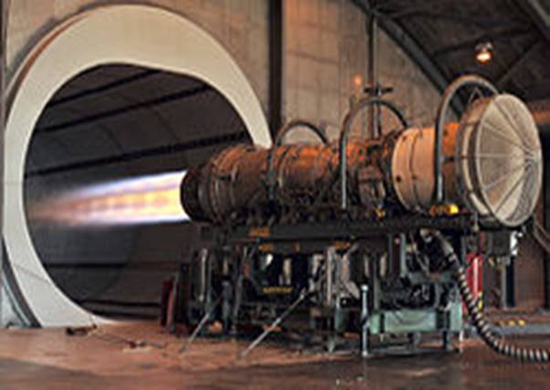
A jet engine at rest, as on a
test stand, sucks in fuel and generates thrust. How well it does this is judged
by how much fuel it uses and what force is required to restrain it. This is a
measure of its efficiency. If something deteriorates inside the engine (known
as performance deterioration) it will be less efficient and this will show when
the fuel produces less thrust. If a change is made to an internal part which
allows the air/combustion gases to flow more smoothly the engine will be more
efficient and use less fuel. A standard definition is used to assess how
different things change engine efficiency and also to allow comparisons to be
made between different engines. This definition is called specific fuel
consumption, or how much fuel is needed to produce one unit of thrust. For
example, it will be known for a particular engine design that if some bumps in
a bypass duct are smoothed out the air will flow more smoothly giving a
pressure loss reduction of x% and y% less fuel will be needed to get the
take-off thrust, for example. This understanding comes under the engineering
discipline Jet engine performance. How efficiency is affected by forward
speed and by supplying energy to aircraft systems is mentioned later.
Efficiency
The efficiency of the engine is
controlled primarily by the operating conditions inside the engine which are
the pressure produced by the compressor and the temperature of the combustion
gases at the first set of rotating turbine blades. The pressure is the highest
air pressure in the engine. The turbine rotor temperature is not the highest in
the engine but is the highest at which energy transfer takes place (higher
temperatures occur in the combustor). The above pressure and temperature are
shown on a Thermodynamic cycle diagram. The efficiency is further
modified by how smoothly the air and the combustion gases flow through the
engine, how well the flow is aligned (known as incidence angle) with the moving
and stationary passages in the compressors and turbines. Non-optimum angles, as
well as non-optimum passage and blade shapes can cause thickening and
separation of Boundary layers and formation of Shock waves.
It is important to slow the flow
(lower speed means less pressure losses or Pressure drop) when it travels
through ducts connecting the different parts. How well the individual
components contribute to turning fuel into thrust is quantified by measures
like efficiencies for the compressors, turbines and combustor and pressure
losses for the ducts. These are shown as lines on a Thermodynamic cycle diagram.
The engine efficiency, or thermal efficiency is
dependent on the Thermodynamic cycle parameters, maximum pressure and
temperature, and on component efficiencies, and duct pressure losses. The engine
needs compressed air for itself just to run successfully. This air comes from
its own compressor and is called secondary air. It does not contribute to
making thrust so makes the engine less efficient.
It is used to preserve the
mechanical integrity of the engine, to stop parts overheating and to prevent
oil escaping from bearings for example. Only some of this air taken from the
compressors returns to the turbine flow to contribute to thrust production. Any
reduction in the amount needed improves the engine efficiency. Again, it will
be known for a particular engine design that a reduced requirement for cooling
flow of x% will reduce the specific fuel consumption by y%. In other
words, less fuel will be required to give take-off thrust, for example. The
engine is more efficient.
All of the above considerations are basic to the engine running on its own and, at the same time, doing nothing useful, i.e. it is not moving an aircraft or supplying energy for the aircraft's electrical, hydraulic and air systems. In the aircraft the engine gives away some of its thrust-producing potential, or fuel, to power these systems. These requirements, which cause installation losses, reduce its efficiency. It is using some fuel that does not contribute to the engine's thrust. Finally, when the aircraft is flying the propelling jet itself contains wasted kinetic energy after it has left the engine.
This is quantified by the
term propulsive, or Froude, efficiencyand may be reduced by
redesigning the engine to give it bypass flow and a lower speed for the
propelling jet, for example as a turboprop or turbofan engine. At the same time
forward speed increases the by
increasing the overall pressure ratio.
Overall Pressure
Ratio and Thermodynamic Cycle
The overall efficiency of the
engine at flight speed is defined as.The
at flight speed depends on
how well the intake compresses the air before it is handed over to the engine
compressors. The intake compression ratio, which can be as high as 32:1 at Mach
3, adds to that of the engine compressor to give the Overall pressure ratio and for the Thermodynamic cycle. How
well it does this is defined by its pressure recovery or measure of the losses
in the intake. Mach 3 manned flight has provided an interesting illustration of
how these losses can increase dramatically in an instant.
The North American XB-70
Valkyrie and Lockheed SR-71 Blackbird at Mach 3 each had
pressure recoveries of about 0.8, due to relatively low losses during the
compression process, i.e. through systems of multiple shocks. During an
'unstart' the efficient shock system would be replaced by a very inefficient
single shock beyond the inlet and an intake pressure recovery of about 0.3 and
a correspondingly low-pressure ratio. The propelling nozzle at speeds above
about Mach 2 usually has extra internal thrust losses because the exit area is
not big enough as a trade-off with external afterbody drag.
Types of Efficiency
Although a bypass engine improves
propulsive efficiency it incurs losses of its own inside the engine itself.
Machinery has to be added to transfer energy from the gas generator to a bypass
airflow. The low loss from the propelling nozzle of a turbojet is added to with
extra losses due to inefficiencies in the added turbine and fan. These may be
included in a transmission, or transfer, efficiency. However, these losses are more
than made up by the improvement in propulsive
efficiency. There are also extra pressure losses in the bypass duct and an
extra propelling nozzle.

Dependence of propulsion
efficiency (η) upon the vehicle speed/exhaust velocity ratio (v/ve)
for air-breathing jet and rocket engines.
The energy efficiency of
jet engines installed in vehicles has two main components:
- propulsive efficiency :
how much of the energy of the jet ends up in the vehicle body rather than
being carried away as kinetic energy of the jet.
- cycle efficiency :
how efficiently the engine can accelerate the jet
Even though overall energy
efficiencyis:
For all
jet engines the propulsive efficiency is highest as the
exhaust jet velocity gets closer to the vehicle speed as this gives the
smallest residual kinetic energy. For an airbreathing engine an exhaust
velocity equal to the vehicle velocityor a equal to one, gives zero thrust
with no net momentum change. The formula for air-breathing engines moving at
speed
with an exhaust
velocity
, and neglecting fuel flow, is
and for a rocket is
.
In addition to propulsive efficiency, another factor is cycle efficiency; a jet engine is a form of heat engine. Heat engine efficiency is determined by the ratio of temperatures reached in the engine to that exhausted at the nozzle. This has improved constantly over time as new materials have been introduced to allow higher maximum cycle temperatures. For example, composite materials, combining metals with ceramics, have been developed for HP turbine blades, which run at the maximum cycle temperature. The efficiency is also limited by the overall pressure ratio that can be achieved. Cycle efficiency is highest in rocket engines (~60+%), as they can achieve extremely high combustion temperatures. Cycle efficiency in turbojet and similar is nearer to 30%, due to much lower peak cycle temperatures.


Typical combustion efficiency of
an aircraft gas turbine over the operational range. Typical combustion stability limits of an aircraft gas turbine. The
combustion efficiency of most aircraft gas turbine engines at sea level takeoff
conditions is almost 100%. It decreases nonlinearly to 98% at altitude cruise
conditions. Air-fuel ratio ranges from 50:1 to 130:1. For any type of
combustion chamber there is a rich and weak limit to
the air-fuel ratio, beyond which the flame is extinguished. The range of
air-fuel ratio between the rich and weak limits is reduced with an increase of
air velocity. If the increasing air mass flow reduces the fuel ratio below certain
value, flame extinction occurs. Specific impulse as a function of speed
for different jet types with kerosene fuel (hydrogen Isp would
be about twice as high). Although efficiency plummets with speed, greater
distances are covered. Efficiency per unit distance (per km or mile) is roughly
independent of speed for jet engines as a group; however, airframes become
inefficient at supersonic speeds.
Consumption of Fuel Or Propellant

A closely related (but different)
concept to energy efficiency is the rate of consumption of propellant mass.
Propellant consumption in jet engines is measured by specific fuel
consumption, specific impulse, or effective exhaust velocity.
They all measure the same thing. Specific impulse and effective exhaust
velocity are strictly proportional, whereas specific fuel consumption is
inversely proportional to the others. For air-breathing engines such as
turbojets, energy efficiency and propellant (fuel) efficiency are much the same
thing, since the propellant is a fuel and the source of energy. In rocketry,
the propellant is also the exhaust, and this means that a high energy
propellant gives better propellant efficiency but can in some cases actually
give lower energy efficiency. It can be seen in the table
(just below) that the subsonic turbofans such as General Electric's CF6
turbofan use a lot less fuel to generate thrust for a second than did the Concorde's Rolls-Royce/Snecma
Olympus 593 turbojet. However, since energy is measured by force times
distance and the distance per second was greater for the Concorde, the actual
power generated by the engine for the same amount of fuel was higher for the
Concorde at Mach 2 than the CF6. Thus, the Concorde's engines were more
efficient in terms of energy per distance traveled.

Thrust-To-Weight
Ratio
The thrust-to-weight ratio of jet
engines with similar configurations varies with scale, but is mostly a function
of engine construction technology. For a given engine, the lighter the engine,
the better the thrust-to-weight is, the less fuel is used to compensate for
drag due to the lift needed to carry the engine weight, or to accelerate the
mass of the engine. As can be seen in the following table, rocket engines
generally achieve much higher thrust-to-weight ratios than duct engines such
as turbojet and turbofan engines.
This is primarily because rockets
almost universally use dense liquid or solid reaction mass which gives a much
smaller volume and hence the pressurization system that supplies the nozzle is
much smaller and lighter for the same performance. Duct engines have to deal
with air which is two to three orders of magnitude less dense and this gives
pressures over much larger areas, which in turn results in more engineering
materials being needed to hold the engine together and for the air compressor.

Comparison of Types
Propeller engines handle larger
air mass flows, and give them smaller acceleration, than jet engines. Since the
increase in air speed is small, at high flight speeds the thrust available to
propeller-driven aeroplanes is small. However, at low speeds, these engines
benefit from relatively high propulsive efficiency. On the other hand,
turbojets accelerate a much smaller mass flow of intake air and burned fuel,
but they then reject it at very high speed. When a de Laval nozzle is
used to accelerate a hot engine exhaust, the outlet velocity may be
locally supersonic.
Turbojets are
particularly suitable for aircraft travelling at very high speeds. Turbofans
have a mixed exhaust consisting of the bypass air and the hot combustion
product gas from the core engine. The amount of air that bypasses the core
engine compared to the amount flowing into the engine determines what is called
a turbofan's bypass ratio (BPR). While a turbojet engine uses all of the
engine's output to produce thrust in the form of a hot high-velocity exhaust
gas jet, a turbofan's cool low-velocity bypass air yields between 30% and 70%
of the total thrust produced by a turbofan system. The net thrust (FN)
generated by a turbofan can also be expanded as:where:
|
ṁ e |
= the mass rate of hot combustion exhaust flow from the
core engine |
|
ṁo |
= the mass rate of total air flow entering the turbofan
= ṁc + ṁf |
|
ṁc |
= the mass rate of intake air that flows to the core engine |
|
ṁf |
= the mass rate of intake air that bypasses the core engine |
|
vf |
= the velocity of the air flow bypassed around the core
engine |
|
vhe |
= the velocity of the hot exhaust gas from the core engine |
|
vo |
= the velocity of the total air intake = the true airspeed
of the aircraft |
|
BPR |
= Bypass Ratio |
Rocket engines have
extremely high exhaust velocity and thus are best suited for high speeds (hypersonic)
and great altitudes. At any given throttle, the thrust and efficiency of a
rocket motor improves slightly with increasing altitude (because the
back-pressure falls thus increasing net thrust at the nozzle exit plane),
whereas with a turbojet (or turbofan) the falling density of the air entering
the intake (and the hot gases leaving the nozzle) causes the net thrust to
decrease with increasing altitude. Rocket engines are more efficient than even
scramjets above roughly Mach 15.
Altitude and Speed
With the exception of scramjets,
jet engines, deprived of their inlet systems can only accept air at around half
the speed of sound. The inlet system's job for transonic and supersonic
aircraft is to slow the air and perform some of the compression. The limit on
maximum altitude for engines is set by flammability – at very high altitudes
the air becomes too thin to burn, or after compression, too hot. For turbojet
engines altitudes of about 40 km appear to be possible, whereas for ramjet
engines 55 km may be achievable. Scramjets may theoretically manage
75 km. Rocket engines of course have no upper limit. At more modest
altitudes, flying faster compresses the air at the front of the engine,
and this greatly heats the air. The upper limit is usually thought to be about
Mach 5–8, as above about Mach 5.5, the atmospheric nitrogen tends to react due
to the high temperatures at the inlet and this consumes significant energy. The
exception to this is scramjets which may be able to achieve about Mach 15 or
more, as they avoid slowing the air, and rockets again have no particular speed
limit.
Noise
The noise emitted by a jet engine
has many sources. These include, in the case of gas turbine engines, the fan,
compressor, combustor, turbine and propelling jet/s. The
propelling jet produces jet noise which is caused by the violent mixing action
of the high-speed jet with the surrounding air. In the subsonic case the noise
is produced by eddies and in the supersonic case by Mach waves. The
sound power radiated from a jet varies with the jet velocity raised to the
eighth power for velocities up to 600 m/s (2,000 ft/s) and varies
with the velocity cubed above 600 m/s (2,000 ft/s). Thus, the lower
speed exhaust jets emitted from engines such as high bypass turbofans are the
quietest, whereas the fastest jets, such as rockets, turbojets, and ramjets,
are the loudest. For commercial jet aircraft the jet noise has reduced from the
turbojet through bypass engines to turbofans as a result of a progressive
reduction in propelling jet velocities. For example, the JT8D, a bypass engine,
has a jet velocity of 400 m/s (1,450 ft/s) whereas the JT9D, a
turbofan, has jet velocities of 300 m/s (885 ft/s) (cold) and
400 m/s (1,190 ft/s)(hot). The advent of the turbofan replaced the
very distinctive jet noise with another sound known as "buzz saw"
noise. The origin is the shockwaves originating at the supersonic fan blade tip
at takeoff thrust.
Cooling
Adequate heat transfer away from
the working parts of the jet engine is critical to maintaining strength of
engine materials and ensuring long life for the engine. After 2016, research is
ongoing in the development of transpiration cooling techniques to jet
engine components.
Operation

Airbus A340-300 Electronic
centralised aircraft monitor (ECAM) Display
In a jet engine, each major
rotating section usually has a separate gauge devoted to monitoring its speed
of rotation. Depending on the make and model, a jet engine may have an N1 gauge
that monitors the low-pressure compressor section and/or fan speed in turbofan
engines. The gas generator section may be monitored by an N2 gauge,
while triple spool engines may have an N3 gauge as well. Each
engine section rotates at many thousands RPM. Their gauges therefore are
calibrated in percent of a nominal speed rather than actual RPM, for ease of
display and interpretation.


What Is a Jet Engine? Evolution of Jet Engine
ReplyDelete